Information
- for power and speed control depending on the size of the input variable
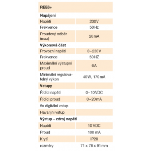
- for single-phase loads with a maximum current of 6 A
- stepless or stepped control
- galvanically isolated control inputs
- emergency input
- thermal protection for triac overload
- adjustable minimum speed
- DIN rail mounting
- for fan speed control, power regulation, dimmers
- operating temperature 0 to +40 °C
- storage temperature -20 to +60 °C
Use
- speed regulation of single-phase motors 230 V / 50 Hz
Description
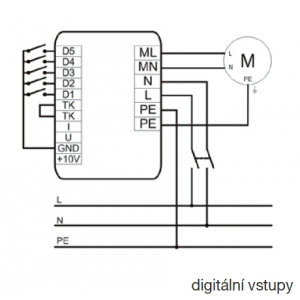
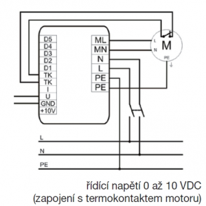
The single-phase triac controller is used for continuous regulation of fans suitable for regulation by changing the voltage depending on the size of the input variable. A voltage input of 0-10 VDC, a current input of 0-20 mA or 5 digital inputs (stages) can be used as the control variable, which are evenly distributed throughout the control range. The activation of a given digital input is a connection e.g. by a transistor with an open collector or a contact against GND on the terminal block.
If no digital input is connected or both analog inputs are zero, maximum triac closure occurs. The decision level for tripping the triac is activation of any digital input or an increase in control voltage above 0.25 V or an increase in current above 1 mA. The minimum speed, adjustable from approximately 60-150 V, can be set by a trimmer located next to the terminal block. The minimum speed can be set at the minimum analogue values of the control voltage or current or when the digital input D1 is switched.
The controller is equipped with an emergency input (terminals TK-TK). When the emergency input is disconnected, the triac is closed. This contact can be used to connect the motor thermocontact. To protect the thermal overload of the triac, a temperature sensor is placed inside the regulator, which reacts in case of overheating as well as failure of the emergency input, i.e. full closure of the triac.
On the front panel there is a triac cooler and an operation indicator. The LED light indicates the state in which the controller is in. In the normal operating condition the indicator light is permanently lit. Changing the speed (opening angle) changes the intensity of the indicator light. Flashing indicates emergency input/thermal overload operation.
A 10 VDC/100 mA voltage source can be used to power external sensors determining the control input variable. The cross-sections of the connecting wires must be dimensioned with regard to the length of the line and the risk of interference.


 Share on Facebook
 Tweet
Tweet Send email