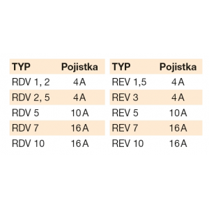
Information
RDV/REV A
Speed controller with power 5-speed switch - operated by switch on cabinet; START STOP by remote selectable switch.
RDV/REV C
Speed controller with 5-stage output switching via contactors - controlled by remote communication switch (DOC) or DO signal from the parent digital system.
RDV/REV E
Speed controller with contactor switching, complete with voltage converter (PN) and 24 V AC/DC source for analog sensor. It is controlled directly by a signal from a remote sensor (0-10 V). In this way, automatic speed control with process variables (air quality, CO2 concentration, temperature, humidity, diff. pressure) is possible.
RDV/REV
The five-stage transformer speed controllers are designed to control asynchronous motors with a resistive armature, which are recommended by the manufacturer for this purpose. The manually operated controllers have a six-position switch on the front panel (OFF, 5 control stages). The toroidal transformers used have low power dissipation and are equipped with thermal protection of the windings by means of thermocontacts.
The regulators are supplied in three functional versions (block diagrams are on the following page).
Description
The transformers, terminal blocks, relays and switches are located in the cabinet. The remote control design is provided with simple dials that allow for Fan Start, Fan Stop, signal Standby and some allow for speed adjustment. For the voltage converter controller, the levels at which switching occurs, the hysteresis of each stage can be programmed. When switching, all stages are first switched off and with a time delay (programmed 6 or 20 s) the next stage is switched on.
Basic technical data
- supply voltage: 230 V (REV), 400 V (RDV)
- output current:
1.5 - 3 - 5 - 7 - 10 A (REV)
1.2 - 2.5 - 5 - 7 - 10 A (RDV)
(the numerical value indicates the maximum phase current in amperes)
- protection: IP54 up to 10 A current, IP20 others
- type designation: The letter after the numeral indicating the current value indicates the regulator version A, C, E
Installation, Maintenance and Service
Each installation must be carried out on the basis of a professional project by a qualified electrical designer or professional company that will make the correct selection of the regulator. Installation and commissioning may only be carried out by a professional electrical installation company authorised under the Trade Act.
- Before installation, the controller must be carefully checked, especially whether any part is mechanically damaged and whether the insulation of the conductors is in order.
- It is advisable to install the power controller close to the fan, e.g. in the machine room or in the ceiling, so that its initial and periodic inspections can be carried out.
- The controller can only be mounted vertically or horizontally on a wall, ductwork or an auxiliary structure. The controller is fastened with four screws in the holes of the controller base.
- Mounting must always be carried out with regard to the weight of the controller, ease of connection of wiring cables, service access and free cooling.
- Care must be taken during mounting to ensure that the interior of the controller, which contains sensitive electromechanical components, is not contaminated. In particular, it must be ensured that no dirt (dust, sand, plaster mixtures, etc.) is introduced as a result of construction activities.
- The remote control can be mounted up to a maximum distance of 50 m from the controller on the wall to the service area.
Caution
When using the controllers, always check that the rated fan current is not exceeded in any position of the controller and in any operating condition of the fan (closed or open dampers, clean or clogged filters, etc.). If the fan motor is not equipped with a thermocontact, the fan overcurrent protection must always be fitted downstream of the controller and the value of the protection element must always correspond to the rated fan current. The regulator protection is located upstream of the speed controller.


 Share on Facebook
 Tweet
Tweet Send email