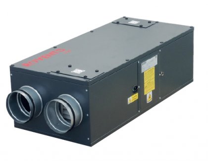
Based on several years of experience with the operation of small heat recovery units, we would like to draw attention to the pitfalls that can occur during self-assembly, which sometimes does not respect the binding installation recommendations of the manufacturer and the general principles of professional installation practice for air handling equipment.
Compliance with all the rules of professional installation is most easily achieved by using a professional installation company that is trained by the manufacturer and thoroughly familiar with the equipment, its installation, the programming of the electronics and the alignment of the HVAC system. We will provide you with a list of authorized installation companies when you purchase the equipment. Guaranteed results can be achieved especially if the project for the small air handling system with heat recovery is prepared by an authorized engineer (according to Act No. 360/1992 Coll. on the practice of the profession of authorized engineers, as amended by Act No. 224/203 Coll. and the changes to the legislation by the entry into force of Act No. 183/2006 Coll, 130/2008 Coll. and 189/2008 Coll. on the recognition of professional qualifications).
In no case do we recommend installing recuperation systems and air distribution systems on your own according to "guaranteed" recommendations of anonymous "experts" who give often curious and dangerous advice on various blogs, which are capable of rendering the systems useless. As they are mostly anonymous, there is no way to verify their intentions, motivation for massive publishing activity or professional competence. In case future users of heat recovery units are interested in deepening their knowledge on this issue, we recommend purchasing professional literature with guaranteed terminology and content (e.g. "Air Conditioning - Gebauer, Rubinová, Horká", "Ventilation and Air Conditioning - Chyský, Hemzal", "Air Conditioning and Ventilation - Rubina, Rubinová" or any other) instead of investigative "googling" without guarantee.
If you still decide to install the equipment yourself or use an installation company that is not experienced with the equipment used or with the installation of HVAC equipment in general, you may encounter the following situations.
1. WATER CONDENSATION AND WATER TREATMENT IN UNUSED PLACES
Water condensation at the supply pipe
Often in do-it-yourself installations, you may find instances where the heat recovery unit is connected through uninsulated piping. Such installation is one of the prohibited installations of heat recovery units. If, for example, air at -12 °C is supplied through an uninsulated supply pipe and the pipe passes through a heated space at +22 °C with a relative humidity of 50 %, more than 1 litre of water per hour will condense on the outside of the pipe towards the room. The condensate flows into the shell of the heat recovery unit where it can disable the electronics and linear bypass drives. Water flows under the casing on the underside of the unit outside the condensate drain spout. When using Elektrodesign air ducts, we recommend a 50 mm insulation thickness of mineral wool (Thermovent).
Water condensation on the exhaust air duct
Uninsulated ductwork on the exhaust air side is one of the prohibited installations of heat recovery units. The same applies to condensate formation and quantity as in the previous case. Likewise, condensate flows into the recovery unit shell where it can disable the electronics and linear bypass drives. The water flows under the casing on the underside of the unit outside the condensate drain outlet. When using Elektrodesign air ducts, we recommend a 50 mm insulation thickness of mineral wool (Thermovent).
Condensate drain freezing
We recommend installing the units in service rooms where the temperature is consistently in the positive range. Some units require installation in rooms with a minimum temperature of +15°C for proper operation of the frost protection. The prescribed inclination of the unit for proper condensate drainage must always be observed, inclination towards the front wall is one of the prohibited installation methods. Some units cannot be installed at all in rooms where the temperature may be below freezing. For others, a trap fitted with some type of heating system (mats, cables, etc.) must be installed to drain the condensate.
Water condensation on and in air ducts
Water condensation can occur inside all air ducts on the exhaust air side if they are not insulated and pass through cold areas (attics, unheated parts of the house, etc.). As water flows through the ducts, it accumulates or flows out at the lowest point of the system. Condensation can occur on all ducts on the fresh air supply side of the unit if they are not insulated and pass through warm areas (e.g., heated areas of the house, etc.). Water runs freely down the ductwork to the areas through which it passes.
2. CONDENSATE DRAINAGE PIPES
Where condensate is discharged from the unit directly into the sewer line, odor may enter the ductwork under certain circumstances. This can occur by the following mechanism.
Exchanger leak damage
Some users often pull or wash the counterflow heat exchanger as part of their "pleasure" with the appliance. Such activity leads to damage to the unit's seal and air leakage between the supply and discharge sides. The unit is tested for leaks upon shipment, therefore this activity is not recommended.
Siphon dry out
If the siphon dries out, and this is commonplace in the summer, odors from the sewer line will permeate the unit and leak into the air ducts and further into the residence. For these reasons, we recommend that condensate be drained into areas where there is another permanently watered siphon or into rainwater downspouts, etc.
3. FREEZE THE RECUPERATION EXCHANGER
In plate heat exchangers, the passage of moist warm exhaust air and cold fresh air supply causes condensation of water vapor on the exhaust air side. This cannot be prevented. Click here to see the conditions at one random operating point of the exchanger that can occur in winter and the amount of water that condenses in the unit and freezes due to the outlet temperature of the exhaust air.
- Condensate in the recovery unit always freezes under certain temperature and humidity conditions. The freezing is eliminated by the so-called "defrosting" process, which takes longer and longer as the outside temperature drops. During this cycle, the unit performs less of its ventilation function because it has to defrost the heat exchanger with internal warm air and reduces the amount of fresh air supply.
- In addition, the unit is quite noisy in this mode because the exhaust fan is trying to push a large amount of warm indoor air through the frozen heat exchanger. Often the sound of falling frost and running water through the condensate drain can be heard from the units. For some units, it is recommended directly in the instructions that high efficiency units can only be operated up to a certain temperature below freezing (usually a maximum of -7 to -8 °C).
- For some units that are operated at supply air temperatures below -7°C, we recommend always using a ground collector, ground liquid exchanger, MBW water heater or MBE electric heater to preheat the air. Another option is a thermostatically controlled mixing damper on the fresh air inlet, which allows the exchanger to be defrosted quickly.
- During the defrost cycle, the lowest external temperature of -7 °C is indicated, which is the limit temperature for the heat exchanger frost protection function, the lower temperature is no longer indicated and the frost protection function is permanently in operation. The indication of the lowest temperature of -7 °C is not a malfunction but is a function of the frost protection.
Freezing of heat exchangers is physically conditioned, is a characteristic of all heat recovery exchangers and can only be reduced by the listed means.
4. FILTER BACKFILL ERRORS
Fault messages that indicate filter clogging (increase in filter pressure drop) are derived from the tachogenerator of EC motors, which provides information about the need for higher speeds to achieve the same flow rate due to the "constant flow" control loop. In winter, this error message is also generated when the heat exchanger freezes, which increases the pressure drop (as do clogged filters) and the fans try to overcome it by increasing the speed.
5. EXCHANGER RPM ERROR REPORTS
A heat exchanger bypass fault message is generated when an actual fault, usually caused by condensate flow as described in items 1 and 2, occurs where condensate flows through the unit shell into the linear drive bypass system and it freezes. The only option is to shut down the unit and defrost it. A service technician visit is always required to repair the ductwork installation causing the condensate to leak and subsequently freeze.
6. ENGINE ELECTRONIC AND FILTER DEFROST FAULTS
Failure of electronic components such as EC motor drivers and suppression filter blocks occurs exclusively after condensate has leaked through the unit shell from uninsulated or improperly installed ducts as described in items 1 and 2. After disassembly, condensate also leaks from the electronics.
7. INSTALLATION, OPERATION AND WARRANTY
The following instructions must always be observed, details are given in the operating and installation instructions, for further information please refer to www.elektrodesign.cz.
- The heat recovery unit must only be connected through sufficiently insulated pipework to prevent condensate dripping onto the unit (risk of damage to the electronics and exchanger/by-pass bypass).
- When operating the unit at extremely low temperatures, fresh air preheating must be used with a ground liquid/air exchanger or an MBE electric heater (otherwise, depending on climatic conditions, freezing of the unit's counterflow exchanger and exchanger/by-pass bypass may occur).
- It is not permitted to connect exhaust air from clothes dryers, fireplaces and furnaces, kitchens and other hot air sources to the heat recovery unit.
- During the winter season, the operator must not use the manual by-pass (by-pass) bypass selector or the by-pass damper may freeze and damage the by-pass damper, heat exchanger.
- Installation of the unit must be in areas with a positive temperature, the condensate drainage from the unit must be made in such a way that under no operating conditions can condensate freeze in the unit or in the drain pipe.
- The warranty does not apply to equipment damaged by failure to follow the binding instructions for installation and use of the unit and the foregoing instructions.
- If the sum temperature of the room exhaust air at the inlet of the unit exceeds 24 °C and the outside temperature is at least 1 °C lower, the "free cooling" function will be automatically activated by switching on the bypass of the heat exchanger/by-pass.
- Depending on the type of function, there may be a delay of up to several minutes between pressing a key on the remote control and the start of the function due to the serial data transmission by the transmitter, this is not a fault but a functional feature.
If your unit is experiencing the faults listed under points 1 to 6, carry out an inspection or contact an installer to check the installation of the unit and air ducts. If such action does not lead to the desired result, please contact our service dispatch.


